HOME > FAQ
| 1-1 | What is INplc? What is the difference with conventional PLC (Sequencer)? |
|
INplc is a PLC product which can run real time OS (INtime®). Of course it is also used as the way of conventional PLCs. There is a diffrence that industrial PC is used as its platform. Regaring details, please refer to "INplc Features" |
|
| 1-2 | Do you have documents of develpment steps (Programming methods)? |
|
We provide you with "users manual" which describes from creating new programs to running the
programs. Development tool 【MULTIPROG】included in INplc-SDK (Development Environment) has a help file which describes every function step by step. You can understand how to use 【MULTIPROG】 by this. |
|
| 1-3 | Can we convert programns of other PLC ladder to INplc? |
| Not available yet. | |
| 1-4 | Does it have the function that outputs pulses per 1 scan? |
Now we don't have functions that outputs pulses per 1 scan. But you can switch contacts ON / OFF per
1 scan by editing the following logic.
|
|
| 1-5 | Regarding areas for variables, contacts and coils | |||||||||||||||||||||||||||||||||||||||||||||||||||||||||||||||||||||||||||||||||||||||||||||||||||||||||||||||||||||||||||
|
Variables, contacts and coils are assigned to the following memories by the settings of I/O address
or Retain/No Retain. ◆ INplc v2.01~
 ◆ INplc v2.10~
 ◆ INplc v3.00~
|
||||||||||||||||||||||||||||||||||||||||||||||||||||||||||||||||||||||||||||||||||||||||||||||||||||||||||||||||||||||||||||
|
※1 ・・・ More than INplc v3.00 doesn't support variable user area. ※2 ・・・ Simulation function of more than INplc v3.00 doesn't support variable user area and shared memory area. |
||||||||||||||||||||||||||||||||||||||||||||||||||||||||||||||||||||||||||||||||||||||||||||||||||||||||||||||||||||||||||||
| 2-1 | Does it have a function that starts / stops PLC opeartion? |
|
You can operate development tool 【MULTIPROG】 from INplc-SDK (development environment). |
|
| 2-2 | Can we start operation retaining data at the time of the stop? |
|
You can use the value of retained data as it is by doing warm start. However, unretained data is initialized. You can use warm start running as [warm] in developemt tool. You can use warm start by [STOP]→[RUN] in INplc panel. |
|
| 2-3 | Can we start operation after initializing data at the time of the stop? |
|
You can initialize all data doing cold start. You can use cold start running as [cold] in developemt tool. You can use cold start by [RESET]→[RUN] in INplc panel. |
|
| 2-4 | Does it have a monitoring funcion (which reads out status of programs and devices on development environment)? |
| You can monitor from developemt tool so that you can check PLC state and I/O value. | |
| 2-5 | Does it have a self-diagnosis function (Controller itself detects abnormity)? | ||||||||||||||||||||||||
It has a functions called SPG (System Program). SPG is a program which is automtically called from
OS of the controller when operation status of controller is error or is changed. You can use the
following sytem programs.
|
|||||||||||||||||||||||||
| 2-6 | Does it have a failure-history function (Save self-diagnosis resulsts as a failure-history to memory)? |
|
It mounts a save-log funcion. It can store errors, changeovers to files. You can see them from operation tool / operation panel. |
|
| 2-7 | Does it have a function that retains device data when power turns OFF? |
|
It mounts retain function. You can retain data by setting [retain variable] when you develop your programs. |
|
| 2-8 | Does it have a watch dog timer function? |
|
You can designate it by task settings.(ms unit) You can do arbitrary processes with detecting watch dog by SYSTEM task. ※ Toward SYSTEM task itself, you can not use watch dog time function.
|
|
| 2-9 | Does it have a function that first scan bit turns ON and second scan bit turns OFF (we often use such a way when system boots)? |
You have to create function blocks with its function on your own.
|
|
| 2-10 | What are available tasks for INplc? | |||||||||||||||
|
You can handle 4 kinds of tasks in INplc according to PLC international standard specification
IEC61131-3. Created programs are executed at arbitrary timings after assigning to tasks. The features of 4 kinds of tasks are as follows.
※Available Maximum Task Number depends on INplc-SDK edition. |
||||||||||||||||
| 2-11 | ●Please tell us the behavior of DEFAULT task. | |||
|
DEFAULT task is a task which runs when other tasks don't run. The operation timing of DEFAULT task depends on system time (minimum timing of INtime® operation). The system time of INplc is 250 μsec. DEFAULT task waits according to the process time after finishing 1 scan process. After finising waiting time, DEFAULT task starts from the next system time. Operation sample of DEFAULT task is as follows.
|
||||
| 2-12 | Can EVENT task run at 500μsec intervals? |
|
Yes, you can. If the load of EVENT task is quite high, process of other tasks are waited, there is a possibility that a watch dog error occurs. So if you'd like to use EVENT task, please consider process contents in advance not to affect other tasks. 
|
|
Please refer to Technical Information on how to issue events of EVENT task from INtime®
applications.
|
|
| 2-13 | ○Regarding task switching |
|
The switching performance of tasks (DEFAULT、CYCLIC、EVENT、SYSTEM) in INplc depends on the performance
of hardware. It means that task switching time depends on the performance of INplc controller which is the target. We disclose data after doing operation verification and data measurement with each maker's and partner's cooperation.
|
|
| 2-14 | Can it detect communication target like FL-net or abnormity of devices etc.? |
| Now the function which detects abnormity is not mounted. ※ Plan to mount in next version |
|
| 2-15 | If we'd like to use EtherCAT®, how many slaves can we connect? |
| Up to 65535 slaves can be connected. However, maximum data number INplc can handle is input:65,532Byte and output:65,532Byte. In case of 16 points digital slave, you can use 32,766 slaves (if all points are used.) |
|
| 2-16 | Does it have a function that stores data of I area / Q area / M area? | ||||||
|
Now the function which collects data of each memory are is not mounted. However, since each memory area is cataloged in ProConOS process, so you can refer to memory information using the following ways.
※ There are some cases that conflict occurs according to refresh timing of each
memory area.
Moreover, we don't assure that referred memory information may not equal to the contents of task. Please understand such situations in advance. |
|||||||
| 3-1 | How many ladder contacts in total can it handle? |
| Please refer to FAQ 4-13 on project limitations of INplc | |
| 3-2 | I've heard about Multi Tasks (Maximum 16 tasks), can we set priority to each task? |
|
You can assign priority by task settings. Maximum priority is [0]. And Minimum priority is [31]. The Maximum priority is called firstly. ※ You can not set priority to SYSTEM task and DEFAULT task.
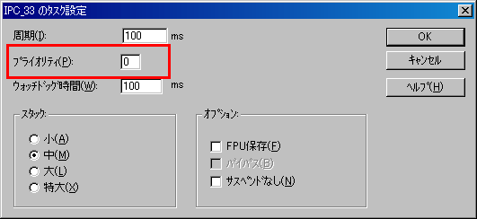 |
|
| 3-3 | I've heard that control period of PLC is 1ms, can we change control period per tasks? |
|
Yes, you can set it per tasks. The useful range of setting values are 1 ~ 32767 ms. ※ You can set it only to CYCLIC task.
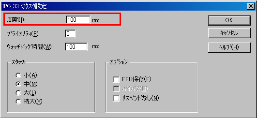 |
|
| 3-4 | Can it use both ST language and LD language at the same time? Can we output from ST to LD contact? |
|
You can use different languages per tasks in 1 project. Though you cannot do I/O of a program (ST language) from another program (LD language) in 2 programs, but you can achieve it by using global variables. Additinally you can not use the grammar of differnet languages in the programs, but you can use function blocks edited by ST language in LD language. 
|
|
| 3-5 | Can it read / write INplc contacts from applications (C language processes) Is it easy to handle multiple lines without load? |
| You can exchange data with INplc by using [INpMac] component. You can exchange data with INplc by VB etc. since DLL and OCX are also provided. ※ INpMac is included in the INplc installation CD-ROM. |
|
| 3-6 | Can it designate continuaton / stop of process when error occurs in PLC? |
| Process stops when an error occurs. If you'd like to keep on doing processes, SYSTEM task detects the error, then you can a function [CONTINUE]※1 in it. ※1 Included in [ProConOS] firmware library of standard equipment. |
|
| 3-7 | How shoud we do if we'd like to set bit ON while PLC is running (RUN state)? (=We'd like to do process detecting RUN / STOP) |
|
You can do arbitrary processes detecting START and STOP by using SYSTEM task. When detects START, then bit turns ON. When detects STOP, then bit turns OFF. "PLCMODE_RUN" which indicates RUN state is defined as global variables. |
|
| 3-8 | Can it stop expansion unit output in stop state? (In case of DO, make all points OFF) |
|
You can do arbitrary processes detecting START and STOP by using SYSTEM task. When detects STOP, then arbitrary outputs turn OFF. Moreover you can do output settings from INplc tool. (This means all outputs turn OFF to I/O drivers.) |
| 3-9 | Can we run 2 INplc in 1 hardware (controller)? |
| No. Now, 1 INplc is for 1 hardware. | |
| 3-10 | Please tell us refresh method which is as an item of IO Configuration. |
 ■ By Task I/O values are automatically refreshed at the first and the end of task execution. You don't have to operate at all. ■ Manually I/O values are not automatically refreshed. You have to refresh in your user programs according to your needs. Concretely speaking, refresh of input value in RD_INPUT_GROUP function block and refresh of output value in WR_OUTPUT_GROUP function block are done. Please see brief explanations on FB/FU help of MULTIPROG. ※RD_INPUT_GROUP function block can not be used in INplc3.0~. |
|
| 3-11 | Regarding I/O space of INplc | ||||||
Here we describe INPUT・OUTPUT space INplc mounts.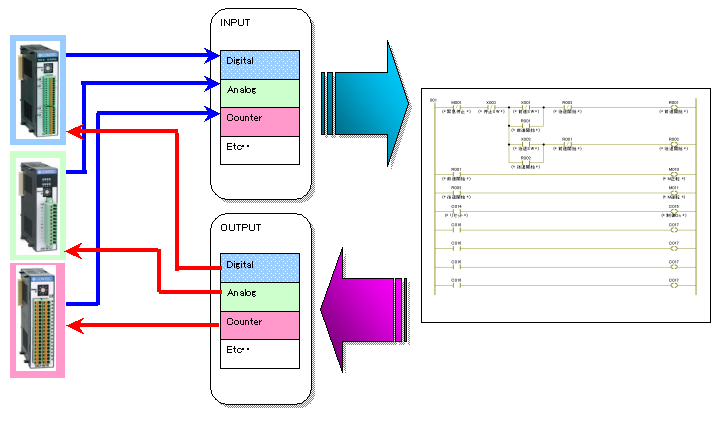
|
|||||||
| 3-12 | Access by"%M". Regarding 【PLC Memory Area】 | |||||||||||||
| Area which can be accessed by "%M" is called as 【PLC memory
area】. PLC memory area consists of the following [Section 0 ~ 3] which is individually independent memory areas.
※1 ・・・ In case of only Section No. [0], you can omit statements of address section parts.
※2 ・・・ If you'd like to make user applications (INtime® applications or NTX applications), you have to purchase 【INtime-SDK】 separetely. ※3 ・・・ More than INplc v3.00 doesn't support this memory area. ※4 ・・・ The simulation function of more than INplc v3.00 doesn't support this memory area. 「1-5 Regarding areas for variables, contacts and coils」 |
||||||||||||||
| 3-13 | Regarding phenomenon of delay generation in I/O or FWL with network device |
|
There are some cases that the problems are IP heap size in Legacy Network.
The defaut IP heap size (IP-BUFHEAPSIZE) is defined as 0x200(512).
Since this size is considered for one interface (network device), so in case of setting for multiple
interfaces, there are some cases of process delay. Regarding setting change, please refer to "23-17 Regarding Proper network resource setting" (Under Constrction). | |
| 3-14 | Can it access to M area (%M section3) from Windows application on the same PC? |
| You can access M area from application programs on the same PC. ※If you'd like to make user applications (INtime® applications or NTX applications) to refer to M area, you have to purchase 【INtime-SDK】 separetely. ■ Reference for M Area Please refer to the followins on M area. FAQ 6-6 FAQ 3-12 FAQ 1-5 |
|
| 3-15 | How is the behavior when BSOD is detected? |
|
There are 2 behavior patterns when BSOD occurs. Pattern 1:Do process for BSOD after BSOD is detected by Event. Pattern 2:Keep on doing process without issuing any Events even if BSOD occurs. Pattern 1:Do process for BSOD after BSOD is detected by Event. If BSOD occurs, the process stops. If you'd like to keep on doing the process, firstly you detect the error in SYSTEM task, then you use function [CONTINUE]※1 in it in order to keep on doing the process. ※1 it is in firmware library [ProConOS] which is provided as standard. Do the following settings. 1.Program→INtime®→INtime® Configuration, start setting tool. 2.Select Node Management as component.  3.In "Windows bug check interception", select "Trap Windows Bug Check Exceptions", then click "save" to save the settings.  4.Do the process for BSOD in SYSTEM task of SPG24 in MULTIPROG project. Keep on doing process without issuing any Events even if BSOD occurs. Issuing event is not done even if BSOD occurs. 【Notice】
Do the following settings.Please pay attention that file I/O can not be used until PC reboot when BSOD occurs. 1.Program→INtime®→INtime® Configuration, start setting tool. 2.Select Node Management as component.  3..In "Windows bug check interception", select "Do NotTrap Windows Bug Check Exceptions", then click "save" to save the settings.  |
|
| 4-1 | Can it copy & paste ladder diagram from other projects? |
| You can copy & paste ladder diagrams.
It is OK for multiple ladder diagrams in 1 project and for multiple INplc-SDK in 1 PC. The steps for copy & paste is same as the ways of Windoows. 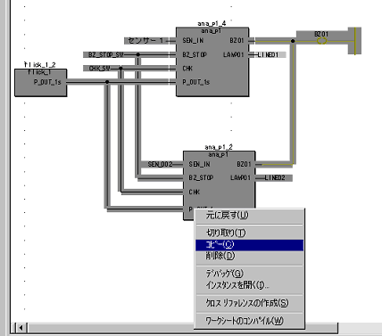 |
|
| 4-2 | Can it write line coments in ladder diagram? |
| You can insert them at any places in graphic work sheets. You surround commnets between parenthesis【( )】and asterisk【*】. You can write it overlapping with other objects. You insert commnets of in graphic work sheets by [comment] dialog. You can input text and can select fonts. In addition, you can automatically insert commnents to left bus-bar of LD circuit or SFC steps. 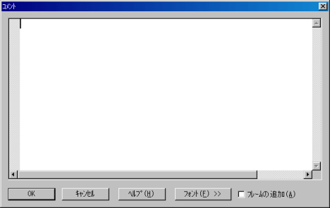 |
|
| 4-3 | How should we do if we'd like to set constant in function block etc.? |
Please select [variables] by right click on input parameter which you 'd like to set in order to set
constants in function block. Please input "TIME#5s" as below figure if you'd like to set "TIME type 5 seconds". Regarding details of data types like TIME type, please refer MULTIPROG help. It has data range and initial value etc. |
|
| 4-4 | Does it distinguish upper-case letters and lower-case letters on variables? |
| You can input it, but it is meaningless because of only display issue. | |
| 4-5 | Can it designate KATAKANA for variable name? |
| In case of Japanese language environment, you can use KATAKANA, HIRAGANA and chinese characters. | |
| 4-6 | Does it have a function "Double Coil Check"? |
| No, now, not checked (No Compile error, too.) | |
| 4-7 | Can it array ladder diagrams? |
| Yes, you can array along right bus-bar with extension edit function. | |
| 4-8 | Can it use numeric operation / comparator of its own making? |
| You can achieve it by creating function or function blocks. You can use it by creating / calling your own function blocks for calculation / comparison with standard equipment function block. 
|
|
| 4-9 | To edit ladder is not renewed at once. There is some cases that to refresh screen is too late. |
| If resource dialog is open, then it is exchanging data with INplc,so there are some cases that refresh process of screen is not stabilized. We recommend to close resource dialog during editing. | |
| 4-10 | Though we insert some objects such as contacts, functions, there are some cases that ther are not reflected on the screen. |
| Please insert them after securing space for objects. | |
| 4-11 | The screen of development tool is garbled. (Windows Embedded environment) |
|
In case that screen of development tool is garbled, please add / modify the following registry in
XPE environment. ※This is for Japanese edition - MUI environment. Please don't apply to other
language environments
[HKEY_LOCAL_MACHINE\SOFTWARE\Microsoft\Windows NT\CurrentVersion\GRE_Initialize]
"GUIFont.Facename"="MS UI Gothic" "GUIFont.Height"=dword:0000000a "GUIFont.CharSet"=dword:00000080
[HKEY_LOCAL_MACHINE\SYSTEM\CurrentControlSet\Control\Nls\CodePage\EUDCCodeRange]
"932"="F040-F9FC" "Unicode"="E000-F8FF" |
|
| 4-12 | Can it create programs which have same logics and output to different targets with ease? |
|
There are 2 ways. 1.Export global variables which is assigned I/O
addresses, then edit the addresses by text file, and then import it.
Firstly you copy the same program. Then you create global variables for each program, assign
global variables to each program.
You can edit I/O address of the same program by modifying I/O address of global variables in a
lump with text file.
2.Bring common logics to function block together,
modify I/O address by providing different parameters to arguments of function block
Firstly you bring common logics to function block together, create multiple programs to which
tasks are assigned, then paste function block to each program. You can modify I/O address by
passing variables assigned I/O address to arguments.
|
|
| 4-13 | Does it have project limitations for program development environment? | ||||||||||||||||||||||||||||||||||||||||||||||||||||||||||||||||||||||||||||||||||||||||||
The following chart describes valid limitation in 1 project. Please refer to the notieces under this
chart.
1) There are some cases that actual limitation values depend on PLC type. 2) There are some cases that actual limitation values are more than above described. In addition, the values depend on resource settings (data area). 3) There are some cases that actual limitation values depend on program capacity 4) Data instance means the number of use that the POU (program/function/function block)is used in other POU and task. |
|||||||||||||||||||||||||||||||||||||||||||||||||||||||||||||||||||||||||||||||||||||||||||
| 4-14 | Can it branch processes like case statements? | ||||||||||||
|
Yes. You can achieve to branch processes by using label and jump in IL/LD/FBD language. ST language can use CASE statements. Please refer to the following sample project. Smaple Overview: Process per 1 sec
|
|||||||||||||
| 4-15 | Can it execute processes (tasks) at arbitrary timings? | ||||||||||||
| Yes. You can run EVENT_TASK at arbitrary timing by use FB"EVENT_TASK" of PROCONOS.FWL. Please refer to the following sample project. Smaple Overview: Start EVENT TASK detecting input rising edge
|
|||||||||||||
| 4-16 | Can it write IF statements / CASE statements without jump functions? |
The following ladder program is an example which compares value of
C001 variable and do SET of the relay with matched terms. |
|
| 4-17 | Does it have a function that first scan bit turns ON and second scan bit turns OFF (we often use such a way when system boots)? |
The following figure indicates that variables of POU turns ON in
RUN |
|
| 4-18 | - |
| 4-19 | Can it execute function only when a certain contact is ON? |
| You can insert function with terms "EN/ENO" to parameters by setting
ON on [function with EN/ENO].
Function is executed when TRUE is input in input parameter EN. When function ends successfully, outpt parameter EN0 outputs TRUE. 【Setting way】 Open option dialog selection [option] of [extension] menu. Parameter(EN,ENO) is added to function by checking ON on [function with EN/ENO] of [graphic editor] tab. |
|
| 4-20 | How should we do if we'd like to use structure variables in LD? |
①Create data type structure ②Create variables of the structure type  ③Double Click contacts, coils, variables which you'd like to assign structure member to  ④Select structure variables from name list  ⑤Select member of structure variables  ⑥You can use it as same as the usual variables. 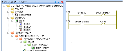 |
|
| 4-21 | How should we do if we'd like to r/w structure variables to memory? |
Please use MEMCPY function or IMEMCPY function of ProConOS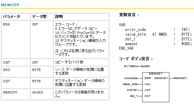 ※If you'd like to use ProConOS function, please add library to ProConOS function. |
|
| 4-22 | Can it change buffer size which is secure in VARCONF when programs is running? |
|
You cannot change the size of VARCONF dynamically. Pleae set your required size when you develop your PLC programs. |
|
| 4-23 | Can it change I/O address (I, Q, M) assigned to variables when programs is running? |
| You cannot change the size of I/O address dynamically. | |
| 4-24 | Can it operate variable addresses? (e.g insert data at I/O address +2 byte of a certain address etc.) |
| You cannot operate addresses in INplc development tool. However, in case of 【Reference / modification for data of I/O address + offset】, you can set I/O address to BYT type array. |
|
| 4-25 | A compile error occurs when VAR_IN_OUT type output of function block is connected to input of other function block. |
| Error occurs since output of VAR_IN_OUT type cannot be connected with
input of other FB. Please refer as follows in MULTIPROG help ・ [Progmming system help] |
|
| 4-26 | How should we do if we'd like to designate variables (=array or structure) other than BYTE type to SRC(BYTE type) parameter of function "IMEMCPY"? |
Since function "IMEMCPY" and DST in ProConOS frimware library is BYTE type, so array or structure
are connected directly,
error occurs during building. The solution might be to share same memory area for INT array and for BYTE variables Such a way enables you to IMEMCPY INT array via BYTE variables.  We describe steps which shares memory area as data copy from INT array 「Int_Arr」to BYTE variables 「byte_arr」as follows. 【Steps】 Data Copy from INT array 「Int_Arr」to BYTE variables 「byte_arr」 (1) Assign M area [%MB3.0] as I/O address of INT array 「Int_Arr」 which you'd like to connect with SRC. (2) Create new BYTE variable [Base], then assign it as I/O addressto the same [%MB3.0].  (3) Connect variable [Base] with SRC of IMEMCPY, then designate other parameters. ※ In case of BYTE array, you can connect the top element, so you connect the top element of [byte_arr] to DST. 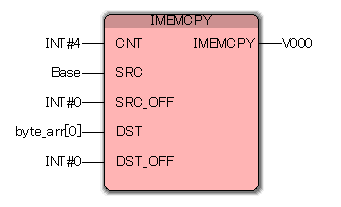 Here, you can copy 「Int_Arr」 to 「byte_arr」. |
|
| 4-27 | Does it have a function which prevents others from changing or browsing projecs and contents of POU? | ||||
| It has protection function to project with password. Please refer to security setting of MULTIPROG help. 【Steps for POU protection】 ①If you'd like to do POU protection, you set the right via [security] tab of the property of target POU. 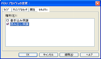
②Set password in [password input] of file menu. 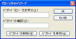 Once password is valid, a key mark is displayed at protected POU icon.  ③You must log in project if you'd like to release the prtectionn. In case of log in project, the way is same as password setting.  You can do not only POU protection but also protection for whole project and for resource. ※ Please refer to security setting of MULTIPROG help. |
|||||
| 4-28 | Can multiple users do operations for a same project at the same time? |
| It has multi user project function.
A server project is saved on a network server. Each user create client projects on his PC so as to
work. Here we describe brief steps. 【Steps】 ①Open project which becomes server project, select [Save as server project] of [project] menu. 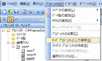 ② Desinate repository of server project. 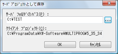 ③Select [Create client project] of [project] menu on PC where you'd like to edit actually. 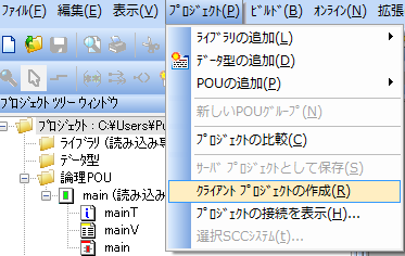 ④Desinate path of server project and repository for client project. 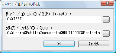 ⑤When you edit project, select items to be edited and check out. 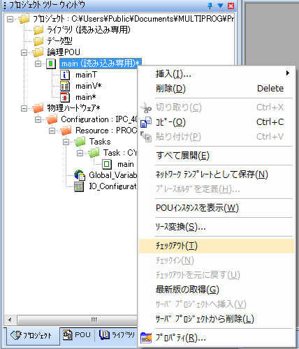 ⑥In case that you finished editing and you'd like to reflet it to server project, then check in. 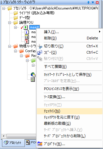 Please refer as follows in MULTIPROG help ・ [Programming system help] |
|
| 4-29 | Does it have a functions that imports / exports variable list? |
|
You can import / export by using text file on setting contents. |
|
| 4-30 | Regarding how to call function block of each language. | |||||||
You can call all functions such as standard function block, FWL function block, users function block
from all languages (FBD・LD・IL・ST・SFC).
Here we describe how to call.
|
||||||||
| 4-31 | Does it have any functions and tools for project managemet? |
|
Please use multi user function for project management ※ Multi user function is only for INplc-SDK Pro+ edition. There are 2 ways in project development by multi user as follows. 1 Project management by standard multi user file system 2 Project management by source control system In 1 Project management by standard multi user file system, management software like VSS(Visual SourceSafe) is not needed, you do exclusive access control so that you can develop 1 project with multi user. It has only exclusive access control, so it doesn't have roll functions such as back function to past data and modification information. In 2 Project management by source control system, On the contrary to 1, you can use VSS etc. so that you can use roll functions such as back function to past data and modification information. ※ INplc products don't have VSS. So please prepare for it if required. Please refer as follows in MULTIPROG help ・ [Programming system help] |
|
| 4-32 | How many bytes for data alignment does it have? |
|
The data alignment is 2 bytes. Please pay attention in cas of using structure.
Ex:If the case is not 2 byte alignments like below,please adjust like padding.
AddressByte 1: BYTE variable 1 AddressByte 2: BYTE variable 2 AddressByte 3: BYTE variable 3 AddressByte 4: BYTE padding AddressByte 5: DWORD variable AddressByte 6: | AddressByte 7: | AddressByte 8: V |
|
| 4-33 | Does it have a way to get data and time? |
|
Please use function block "RTC_S" in ProConOS library. ※ For more details, please refer to FB/FU help - [ProConOS function block]→[RTC_S]. |
|
| 4-34 | Does it have a way to get day of the week? |
|
Currently it doesn't have FU / FB which get the information of day of the week. Please create function which returns calculation results using Zeller's congruence from date. Please refer to the following sample project. ※Please use it as user function.
|
|
| 4-35 | How shoud we do if we'd like to run consecutively FB which runs at rise time? |
|
Please use controlling rising edge in loop process. Please refer to the following sample project. |
|
| 4-36 | Does it have a function that has a rule such as F relay of MITSUBISHI sequencer? |
|
Though it is not a notification by relay etc., but you can check "with or without abnormity" by
using system task. As for system task etc., please refer to「2-5 Does it have a self-diagnosis function (Controller itself detects abnormity)?」. |
|
| 4-37 | Does it have a function similar to inverse (INV) of MITSUBISHI sequencer? |
|
You can inverse the calculation results by the following function. 【Function】NOT 【Description】This bool bit calculation function inverses the operand connected with input parameters as bit unit. |
|
| 4-38 | Does it have a function similar to MC/MOV/MOVP/INCP/DINCP/DMOVP of MITSUBISHI sequencer? |
|
You cannot change memory pointer. In case of how to achieve in INplc, please refer as follows. Please refer to the following sample project. |
|
| 4-39 | Does it have debugging methods with running programs in only development environment? |
|
There is a way that you execute ladder progarams only in development environment to do
debugging. ※ As for I/O, not use actual I/O device but use I/O Simulator. In case of using I/O Simulator, pleae set the following setting items. ① Select Resource on project tree of MULTIPROG, then select setting items by right click. 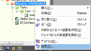 ② Select "Simulation 1" on port for rerlease setting, then click OK button. 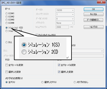 ③ Double click IO_Configuration on project tree of MULTIPROG to display I/O configuration screen. 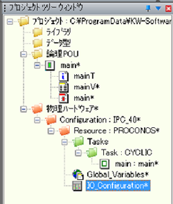 ④ Change "Board I/O moudle in INPUT/OUTPUT"to User Definition. Double click I/O group which you'd like to change, then display property screen. If you'd like to create newly, please add [add] button. 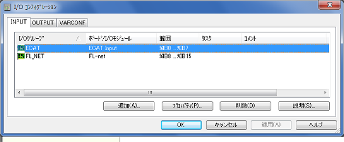 ⑤ In case of change, other than Board I/O moudle, remain current state as it is. Please set accroding to I/O module to be used in case of new. Select [user defnition input] to select "Board I/O moudle". Click [Driver Parameter] button to display parameter screen. 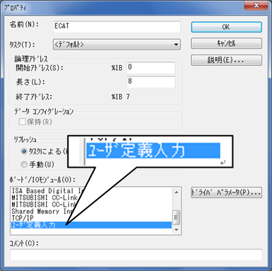 ⑥ Input SIMIO" on [Driver name], then click "OK" button. 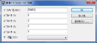 ⑦ If you have changed "Board I/O moudle in INPUT/OUTPUT"to User Definition, then the steps are complete. 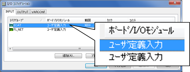 Regarding how to use I/O Simulator. please refer to "MULTIPROG quick start guide". |
|
| 4-40 | Please tell us how to download programs which is confirmed MULTIPROG Simulator to INplc controller. |
|
Please change settings from using simulator to downloading to INplc controller by the following
steps. ① Select Resource on project tree of MULTIPROG, then select setting itemsn by right click. 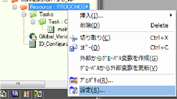 ② Select "DLL" on port of release setting, input "-ip 192.168.3.1 -TO2000" as parameter, then click "OK" button. ※「192.168.3.1」 is default IP address of INplc controller. Please change IP address if required. 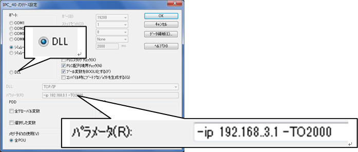 ③ Double click IO_Configuration on project tree of MULTIPROG to display I/O configuration screen. 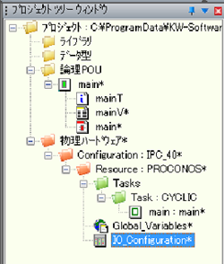 ④ Change "Board I/O moudle in INPUT/OUTPUT"to User Definition. Double click I/O group which you'd like to change, then display property screen. If you'd like to create newly, please add [add] button. 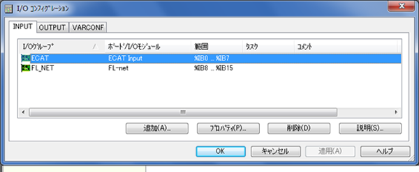 ⑤ Select "Board I/O moudle" from [user defnition input] Please set paramter bu clicking [Driver Paramater] button Select [user defnition input] to select "Board I/O moudle". Click [Driver Parameter] button to display parameter screen. ※ Please refer to each user manual since driver parameters are differnet accoring to "Board I/O moudle" 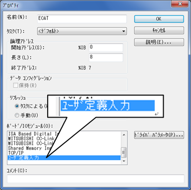 |
|
| 4-41 | Does it have a function that FBD aligns functions and function block FB? |
|
It is easy to asign your programs by using LD. LD can use function and function block as FBD. |
|
| 4-42 | Can we set not to change execution order of function or function block even though the position is moved? |
|
In case of function unit or function block unit, you can't fix the order. but to a certain blcok
unit, please write combining with SFC. ※SFC is suited for order control based on state transition. |
|
| 4-43 | Does it have a function for contact of rise and fall? |
|
No, it doesn't now. Please use combining with edge detection type - function block (R_TRIG・F_TRIG). |
|
| 4-44 | A compile error occurs when a file is exported as the file formant of XML file and is imported again. |
|
If compile error occurs after importing, please display the FB/FU by double clicking error message
in error windows. Execute "refresh FB/FU" after right clicking the FB/FU, then compile is available. |
|
| 4-45 | How many global variables are available? |
|
Maximum available global variables are about 30000. (This specification is for more than INplc3.00
version of INplc-SDK Pro+). ※Except above, though you can declare, but error occurs when making. |
|
| 5-1 | Can it do operatioal test without conneting actual I/O? |
| Yes, you can if you use I/O simulation function of developent tool. (Numbers of I/O points are variable.) | |
| 5-2 | Can it change programs witout stopping PLC? |
| You can modify programs without stopping PLC by using [download of change] from developent tool. | |
| 5-3 | Does it have a function that displays process time of running programs? |
| The information can be displayed in "resource dialog" of developent tool. | |
| 5-4 | Does it have a function of step execution? |
|
You can stop executing your programs at designated code position by setting break points in online
mode. After that, you can keep on doing step executions, too. Moreover, you can release break points in a lump. ・The following figure describes an example of ST worksheet of online mode, that has 2 break points (line 4 and line 15) and the programs stops at (line 15). 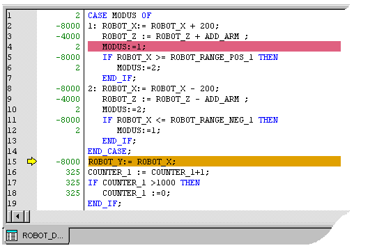 |
|
| 5-5 | Does it have a function of program upload? (It means that it deploys running PLC prorams to development environment) |
|
You can [upload] if source files are downloaded. Source files are downloaded to PLC if you check [include source in download dialog] . |
|
| 5-6 | Can it compare programs in development environment with running PLC programs (check difference etc.)? |
| You can extract the differences of variables, tasks in 2 projects by using [project comparison] of development tool。 | |
| 5-7 | Can it back up PLC memory status? (e.g. bring back data to maintain it) |
| Currently this function is not mounted. Plan to support it in future. | |
| 5-8 | Can it display the time for processing? |
| You can get the maximum value of the required time for the logic from
the structure included in internal memory. |
|
| 5-9 | There are some cases that debugging mode is not displayed if we move to debugging mode without downloading. |
| It occurs if you use development tool MULTIPROG4.8. As the interim procedure, you close all worksheets in workspaces of development tool, then open again. Then it is cleared. In next version, it will be cleared. | |
| 5-10 | Doesn't it have a scheme measuring process time per POU? |
| There is no way of measuring process time per POU. | |
| 5-11 | What shoud we refer for how to use logic analyzer of MULTIPROG? |
Please refer to [PLC help]-[general PLC online help]-[logic analyzer] of MULTIPROG help as
follows.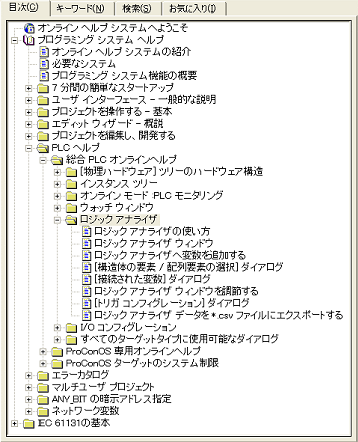 |
|
| 5-12 | Does it change some contact values without opening degugging dialog? |
| You can change values by clicking contacts if [toggle bool variables]
is set. ※ only support for BOOL type. ※ In case of variables which are set as I/O address such as %IXxx.x, it is compulsory setting. ※ In case of variables for which I/O address is not set, it is overwrite mode. 【How to set】 Open variable worksheet and check on [TB] check box (right edge) of taget variable. ![[TB] Check box](images/FAQ_051201_E.png) After that, make project->download->swich to debug mode . Select [toggle bool variables] mode from [online] menu. Please refer to the index of MULTIPROG help for more details. ・ [Programming system help] |
|
| 5-13 | Does it have a method to check the values of member variables of structure variables in debugging mode? |
①Select "Open watch window" by right click. ②Select structure you'd like to confirm, then select "Add to watch window" by right click  ③Select member or structure variables you'd like to see.  ④You can check the contents of selected variables. 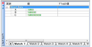 |
|
| 5-14 | Can it confirm the status of variables in a lump which are compulsorily set in debugging mode? | ||
You can confirm it in [Compulsory Setting] tab by clicking resource
dialog [information].
|
|||
| 5-15 | Can it measue the execution time of task? |
| Internal variables of INplc has task process time as tick unit. You
can rasp approximate process time by it. |
|
| 5-16 | Can it confirm the status of specific variables during debugging? |
You can check / modify status of variables by using watch window. Please refer to FAQ 5-13 on how to use watch window. |
|
| 5-17 | Can it change numeric formats during debugging? (e.g. from hexadecimal to decimal) | ||||||||
You can select notation system of numeric on [display value] on debug
dialog.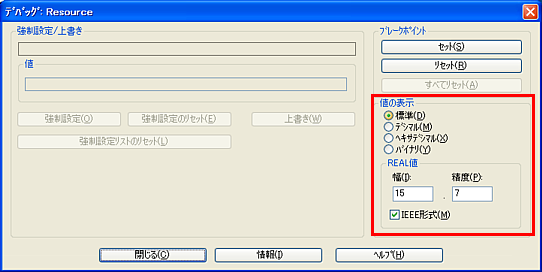
|
|||||||||
| 5-18 | There are some cases that variables are initialized if running ladder is modified and downloaded. |
|
Please use not "download" but "download of change" if you'd like to reflect current status. ※ Please refer to "download of change" from [key word] tab of MULTIPROG help for more details. |
|
| 5-19 | There are some cases that downloaded projects are removed when the power of INplc controller is turned off. |
|
Please download in boot porject setting when you "download". ※ Please refer to "boot porject" from [key word] tab of MULTIPROG help for more details. |
|
| 5-20 | Are there any ways that retains variable values in next boot time even though the power of INplc controller is turned off? |
|
Please do retain setting for variables you'd like to retain. ※ Please refer to "retain variable" from [key word] tab of MULTIPROG help for more details. |
|
| 5-21 | How should we do if we don't have INplc controller itself or INplc controller doesn't have actual I/O? |
|
Please use simulation function. You can do debugging in development environment by using "user defnition input" at I/O configuration if the I/O does not exist. ※Please refer to "MULTIPROG quick start guide" on programming / operation way of simulation. ※Please refer to "simulation" from [key word] tab of MULTIPROG help for more details on simulation. |
|
| 5-22 | There are some cases that the values of FB are wrong. |
There are some cases that initial values are not correct if you connect type conversion FB with FB
directly. Please use type conversion FB not directly but separetely. 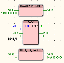
|
|
| 6-1 | Which version of INtime® has INplc corresponded to? How about 2.14? |
| Currently INplc has supported for more than INtime® 4.2 version. If you use the previous version, you must upgrade your INtime® version. |
|
| 6-2 | Regarding a cooperation method between INplc and user applications (Windows/INtime®) |
|
If you'd like to communicate between ladder programs INplc uses and user applications for Windows or
INtime®, you can achive the following ways. 1)I/F for Memory (INplc ⇔ Application)
2)Event Notification (Application⇒ INplc) 3)I/F for INtime® Object (INplc ⇔ Application) ■ I/F for Memory  This functions is an interface for memory using MemDrv I/O driver which is mounted to INplc as standard. As the following figure, you can exchange data with INplc ladder programs via shared memory of MemDrv I/O driver. Shared memory of MemDrv I/O driver is created as the below mentioned name in "ProConOS" process. You read / write using handles which Lookup( LookupRtHandle() / ntxLookupNtxHandle() ) shared memory in your application programs.  ■ Event Notification  This is a function that notifies to INplc task "EVENT" from user applications.  ■ I/F for INtime® Object  This functions is an interface using INtime® objects (semaphore, mailbox, shared memory) which are mounted to INtime® as standard. 
|
|
| 6-3 | Can INtime® open ladder diagram of PC-PLC? Can INplc convert to ladder? |
| Now conversion function to ladder is not mounted. | |
| 6-4 | How many priorities for INtime® is each task? | ||||||||||||||||||||||||||||||||||||||||||||
INtime® priorities for each task are as follows.
※ Task priority is only for CYCLIC Task and EVENT Task. You can not set to DEFAULT
Task and SYSTEM Task.
※ This contens is based on INplc v2.00.
|
|||||||||||||||||||||||||||||||||||||||||||||
| 6-5 | Priorities "16 - 31" are all same in INtime®. Are these priorities handled as the same priorities in INplc, too? | ||||||||||||
|
Yes, they are same priorities. In case of same priority, tasks including(DEFAULT Task) are executed by turns from bottom to top of MULTIPROG project window.。
|
|||||||||||||
| 6-6 | What is "M area"? | ||||||||||||||||||||||||||||||||||||||||||||||||||||||||||||||||||||||||||||||
|
【M Area】is a [Shared Memory Area] which INplc has. You can exchange data with user applications (INtime® applications or NTX applications) by using this area. 1) M Area Basic Information
◆ INplc v2.01~
2) How to use M Area
◆ INplc v2.10~
◆ INplc v3.00~
※ The simulation function of more than INplc v3.00 doesn't support
shared memory area.
◆ PLC Program side When you make your progarms, you must assign M area to I/O addresses of [variables] or [contacts / coils]. When you write I/O address, you add section number [3] which means M area before address offset. ※ Regarding section of "%M", please see here. Ex 1) In case that yoiu'd like to access 2nd bit of 10th byte o fM
Area by single bit size
◆ User Application side%MX3.10.2 Ex 2) In case that you'd like to access 20th byte of M Area by WORD size %MW3.20 You look up ["PRO_MAREA"] cataloged at ProConOS process and use obtained memory handle with mapping. ※ If you'd like to make user applications (INtime® applications or NTX
applications), you have to purchase 【INtime-SDK】 separetely.
|
|||||||||||||||||||||||||||||||||||||||||||||||||||||||||||||||||||||||||||||||
| 6-7 | Can it use both Virtual Ethernet of Network7 and Virtual Ethernet of Legacy network at the same time? |
| You can not use Virtual Ethernet of Network7 and Legacy network at the same time. | |
| 7-1 | "MULTIPROG limits resources" is displayed when we build projects in MULTIPROG. |
There are some cases that the following messages are displayed during building (compiling). Causes of this error might be " Non License Registered to MULTIPROG" or "USB Dongle Key for MULTIPROG Not Inserted" . In case of "Non License Registered to MULTIPROG" or "USB Dongle Key for MULTIPROG Not Inserted", MULTIPROG is acted as the trial version, so there are some resource limitations. |
|
| 7-2 | It seems that the action is stopping in the halfway of the downloading when we use simulation function of MULTIPROG. |
|
There are some cases that downloading is stopping in the halfway as follows when you use simulation
function according to PC system environment. Since this is a phenomenon which occurs when simulator boots initially after Windows start, so you can enjoy it by the following operation. 【Solution】 Finish "EasySim.exe" on task manager to interrupt MULTIPROG download, and you can do normal operation as usual. |
|
| 7-3 | CPU load 100% error occurs when we use CONTINUE function at SYSTEM task [Zero Division] process. |
You can not use CONTINUE function in the process of SYSTEM task which detects SPG11. Tasks where "hardware exeption" such as 0 division occurs is stopped compulsorily by system. Tasks stopped compulsorily cannot resume even if it uses CONTINUE function, so it cannot finish task work, so CPU Load 100% error is detected. If you'd like to keep on doing process afere 0 division, please use HOT_RESTART CONTINUE function. ※ "CONTINUE" and "HOT_RESTART" are included in PROCONOS.FWL. Regarding details of function, please refer to FB/FU help. |
|
| 7-4 | Error occurs during downloading if we designate 65535 as start address in I/O group setting of IO_Configuration |
This error occurs when it is beyond the accessible range of I/O space (I area, Q area). Vaules can be set as I/O start address are [0~65531] since the size of the accessible range of I/O space (I area, Q area) is 65532 bytes. This error also occurs when the total of [start address] and [length] is beyond 65532 bytes. ※ Please also see as follows: "1-5 Regarding areas for variables, contacts and coils"・・・ accessible range of I/O space (I area, Q area) "3-11 Regarding I/O space of INplc"・・・ overview for start address and length of I/O space (I area, Q area) |
|
| 7-5 | "Run time error '429':ActiveX component cannot create object." is displayed when we use INplc Tool. |
|
Here cases of Windows 7 are reported. Please reinstall after release user account control (UAC). ※Please refer to "Regarding how to release user account control (UAC) in INplc-SDK setup guide. |
|
| 7-6 | "Internal error. Firmware function or function block 'XXX' is invalid" is displayed when we download. |
|
Firmware libraries for downloaded projects are not insatalled to INplc controller. Regarding how to install / set, please see the following documents. ・ Setup guide ・ User guide ※Above documents are in Windows→"All Programs"→"INplc"→"Expansion Unit manual" in your development environment. |
|
| 7-7 | "Operand can not be used or beyond the area." is displayed when we build. |
|
There are some cases that I/O addresses of variables are outside the definition of I/O cofiguration
of MULTIPROG. ※Others, please search in MULTIPROG help. |
|
| 7-8 | "POU '○○○○○○' is not available." is dsisplayed when we build projects in MULTIPROG. |
|
This message '○○○○○○' can not be used in this version or this product. Since the functions listed in FB/FU help of MULTIPROG is common, so functions cannot be used might be also listed. Please understand such situations. |
|
| 7-9 | Connection time out occurs when we use simulation function of MULTIPROG |
|
Since PLC engine of simulation function has not started, so timeout occurs. This phenomenon depends on incorrect registration of simulation function to Windows when INplc-SDK(Express) is installed. It is cleared by re-registering simulator function as follows. (※This has been modified after INplc v3.06.)
① Open command prompt as admistrator right on the environment where INplc-SDK is installed.
② Do the followins commnads
"%ALLUSERSPROFILE%\ADE\EASYSim eCLR 1\EASYSim.exe" /regserver
"%ALLUSERSPROFILE%\ADE\EASYSim eCLR 2\EASYSim.exe" /regserver |
|
| 8-1 | Regarding application for INplc RSI-CCIE(CC-Link IE) |
| If you'd like to use CC-Link IE from INplc, you have to purchase RSI-CCIE separetely. Regarding details, refer to Application steps for INplc RSI-CCIE(CC-Link IE)(Under Constrution). | |
| 8-2 | Regarding application for INplc RSI-ECAT(EtherCAT®) |
|
If INplc RSI-ECAT does not run correcly after introducing, please check the folloing points. ① Is the LAN port to be connected correct?
In case that you install EtherCAT® Studio to INplc conroller,、
② Does it use the latest ESI file for the slabe to be used?
please pay attention that a LAN port for EtherCAT® Studio (= Windows) is different from another port for INplc controller (= INtime®).
You can get the latest ESI file for slaves from vendor's website.
③ Can it change master state to Operational in EtherCAT® Studio?
For more details, please ask the vendor. Please check whether you can change master state to Operational in
EtherCAT® Studio.
④ Can it do I/O in EtherCAT® Studio?
Please check whether you can do I/O in EtherCAT® Studio.
⑤ Have you sent an XML file created by EtherCAT® Studio to INplc controller using INplc tool?
Some slaves needs to use their own tools to do settings. So please check it.
⑥ Didn't you use memory area that PDO mapping is done? (For CoE FB user)
Please do operation check using RSI-ECAT sample. (for INtime® user) You can not use FB related with CoE to memory area for PDO mapping.
|
|
| 8-3 | Regarding application for motion boards by Hivertec |
| If the board can not be found, please check whether board ID is set by serial from 1. | |
| 9-1 | What is "INplc-OPC Server "? |
| Regarding overview of "INplc-OPC Server", refer to Regarding OPC server "INplc-OPC Server" (Under Constrution). | |
| 9-2 | I cannot understand how to use "INplc-OPC Server " |
|
Regarding how to use INplc-OPC Server, refer to Regarding Connection settings between INplc-OPC
Server and INplc-Controller (Under Constrution). |
|
| 9-3 | How should we do if we'd like to communicate with OPC client located in other PC? |
| Regarding how to use OPC communication via netwrok, refer to Basic
setting to use OPC communication (remote connection) (Under Constrution). |
|